Nisal Ovitigala
Manufacturing Innovation Engineer
About Me
- Current Position:Manufacturing Innovation Engineer - New Balance
- Education:B.Sc in MechE, MIT 2021
- M.Sc in Data Science, NEC 2026
- Residence:Somerville, MA
- Hometown:Sri Lanka
Hello There!
A Manufacturing Innovation Engineer (Robotics & Automation) at New Balance and former Test Engineer at Formlabs with a Bachelor's in Mechanical Engineering from MIT. I specialize in bridging mechanical, electrical, and software engineering to take complex electromechanical systems from conceptualization to factory deployment.
At New Balance, I spearheaded testing efforts, developed novel gripper technologies, and created vision-based QC systems. At Formlabs, I tested diverse electromechanical systems, thermal systems, and embedded software.
These experiences make me an adaptable and effective full-stack hardware engineer.
My Resume
Download my resume here
-
Work Experience
-
Innovation Engineer
New Balance Athletics (March 2023 - Present)- Integrated Allen-Bradley PLCs, Universal Robots, Ignition SCADA, and custom hardware to engineer a ground-up automated textile assembly cell scaling to 1,200 units/day
- Utilized SolidWorks to rapidly prototype and consolidate a 6-component hardware assembly into a single custom sheet metal bracket, eliminating critical alignment errors and reducing BOM complexity. Managed design changes through PDM
- Developed Allen-Bradley ladder logic and converted DC to stepper control for precision positioning with stall-detection and custom calibration routines. Fused multi-node sensor arrays data for presence detection and engineered architecture to SIL 2 safety standards
- Served as primary technical POC for a ~$100K project with contract manufacturers. Mitigated 3-month lead-time delays by identifying and validating alternative hardware components to maintain deployment schedules
- Built inspection cells using Matrox Imaging Library and custom ML models to automate IQC, achieving 0.5mm feature detection and eliminating operator subjectivity
- Conducted climate-controlled testing to disqualify electrostatic grippers due to environmental sensitivity. Validated multiple gripper technologies for production and initiated custom vendor development for next-gen hardware
- Established testing standards such as accelerated lifetime testing to identify and remediate critical failure modes before production, ensuring system stability over high-cycle operation and minimizing system downtime
-
SLS Test Engineer
Formlabs (July 2021 - February 2023)- Eliminated the second-largest hardware failure and a leading cause for RMA on the Fuse 1 by implementing and validating thermal system upgrades for improved function, safety and lifetime, and established quantitative methods to monitor system degradation
- Optimized SLS printing performance by reducing total print time by 20% through a variety of firmware changes while testing and improving lifetime of relevant wear components
- Investigated and root caused the largest sensor failure in the SLS lineup, collaborating with manufacturing, sourcing, and sustaining teams to implement both short-term and long-term mitigation strategies
- Identified NEC compliance risks for the Fuse 1+ and validated printer functionality for worldwide usage in edge-case environmental and electrical conditions
- Created automated fiber laser characterization tool, resulting in accurate and efficient data collection of LIV curves, thermal response, and high-frequency switching response
- Developed and integrated various test setups with data logging for internal use, including environmental chambers, pneumatic impact testers, and thermal lifetime testers
-
Haptic Feedback System Developer
MIT Micro/Nano Lab (September 2020 - June 2021)- Developed a 1DOF haptic feedback controller to interface with an Atomic Force Microscope to allows users to feel attractive and repulsive force that occur on the nano scale.
- Research paper about project was accepted and presented at the 2022 ASEE annual conference (Link to paper)
- Collaborated with AFM manufacturer to obtain custom firmware to obtain real-time control and feedback between haptic device and AFM
-
Automation System Developer
MIT Micro/Nano Lab (June 2020 - September 2020)- Enhanced remote learning during pandemic for undergraduate and graduate students by modifying a compound light microscope to controlled and viewable through the internet
- Increased motion precision by three orders of magnitude to achieve micrometer-level precision, allowing user to obtain Z-height information on specimen without additional hardware
- Improved user experience by implementing photo/video recording features, a GUI for a live coordinate readout, and a homing/parking sequence for easy slide replacement
-
Robotic Systems Researcher
MIT d'Arbeloff Lab (January 2020 - March 2020)- Developed 1' tall 3D printed robotic legs to test and validate motion control algorithms prior to testing algorithm on 6' tall robot attached to people
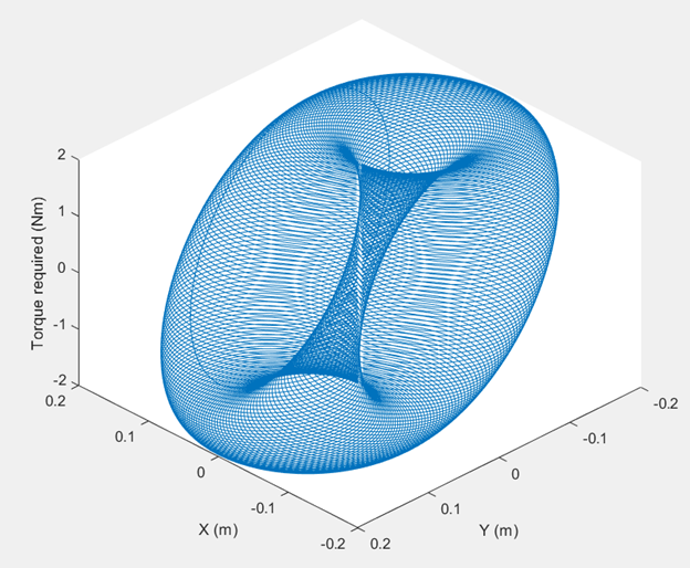
- Developed internal MATLAB scripts to visualize robotic limb workspace and torque requirements to rapidly prototype limb geometry for varying applications
- Developed a hybrid force/position walking algorithm by interfacing high-level motion planning MATLAB code with embedded C++ motion controllers
-
Mechanical Engineer
TILT (January 2020 - June 2022)- Designed a low-cost modular attachment to allow wheelchair users to traverse staircases in areas lacking proper accessibility infrastructure
- Analyzed data to improve design criteria from alpha prototype user tests conducted with over 20 wheelchair users in India
- Iterated design using DFM and DFA criteria to decrease scrap material and reduce uncertainty during assembly
-
Innovation and Performance Intern
Keolis Commuter Services (June 2019 - September 2019)- Investigated and eliminated oil pump malfunction in locomotive fleet, reducing unscheduled maintenance occurrences by over 15%
- Designed and integrated filter cleaning procedures in locomotive maintenance , saving $30,000 per locomotive in annual upkeep cost
- Designed locomotive 3D models and analyzed fluid simulations of exhaust gasses, enabling rapid iteration of body panel designs to eliminate carbon buildup on headlight surfaces
-
Education
-
New England College
Masters Degree - 2023 - 2026Major: Data Science and Analytics
-
Massachusetts Institute of Technology
Bachelors Degree - 2017 - 2021Major: Mechanical Engineering
Focus: Electromechanical Systems, Robotic and Control Systems
Concentration: Music Technology
Relevant Coursework: Mechanics and Materials, Dynamics and Controls, Thermal-Fluids Engineering Robotic Systems, Precision Machine Design,Bio-Inspired Robotics, Numerical Computation for Mechanical Engineers, Instrument and Measurement, Design and Manufacturing, Product Design, Mechanical Engineering Tools, Fundamentals of Programming, Signals and Systems, Electronics for Mechanical Engineers
-
Gateway College Sri Lanka
High School - 2013 - 2017Focus: Science and Technology
Role: Deputy Head Prefect
Awards and Clubs: Monash University Future Leader Award, Fulbright Scholar Program, Head of Community Service Club, Edexcel High Achiever Award, SLMUN 2014 Organizer
Projects
Sensus
In this class, I and 16 other students work together as a product development firm throughout the semester. We start by selecting an idea and then running it through different phases such as high-level physical modelling, detailed CAD design review and final manufacturable product.
We decided to make a medical device that automates testing for peripheral neuropathy in users feet by mimicking the Semmes-Weinstein test where a doctor would touch the patients foot at different locations with a thin wire filament and asks them if they felt the touch.
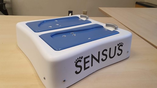
The final product. The thermoformed blue inserts are removable so that different ones can be used for people with different foot sizes. This is so that the main housing can be manufactured without changes to tooling. The aluminum heel liners are used as a guide for the user to place their feet. They also act as a capacitive touch sensor to tell the server that the user has placed their feet on the device
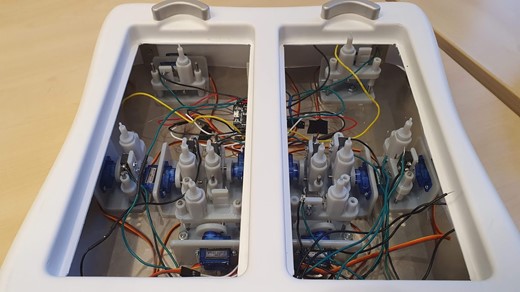
A look at the internal housing and mechanisms
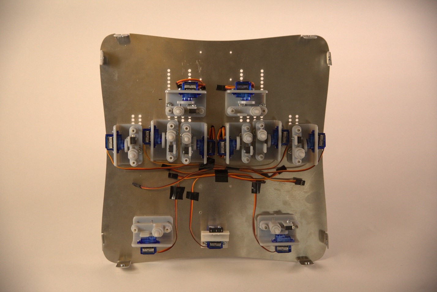
The stainless steel baseplate of the device without the thermoformed housing. There are multiple hole cutouts so that the mechanisms could be adjusted to accomodate various foot sizes
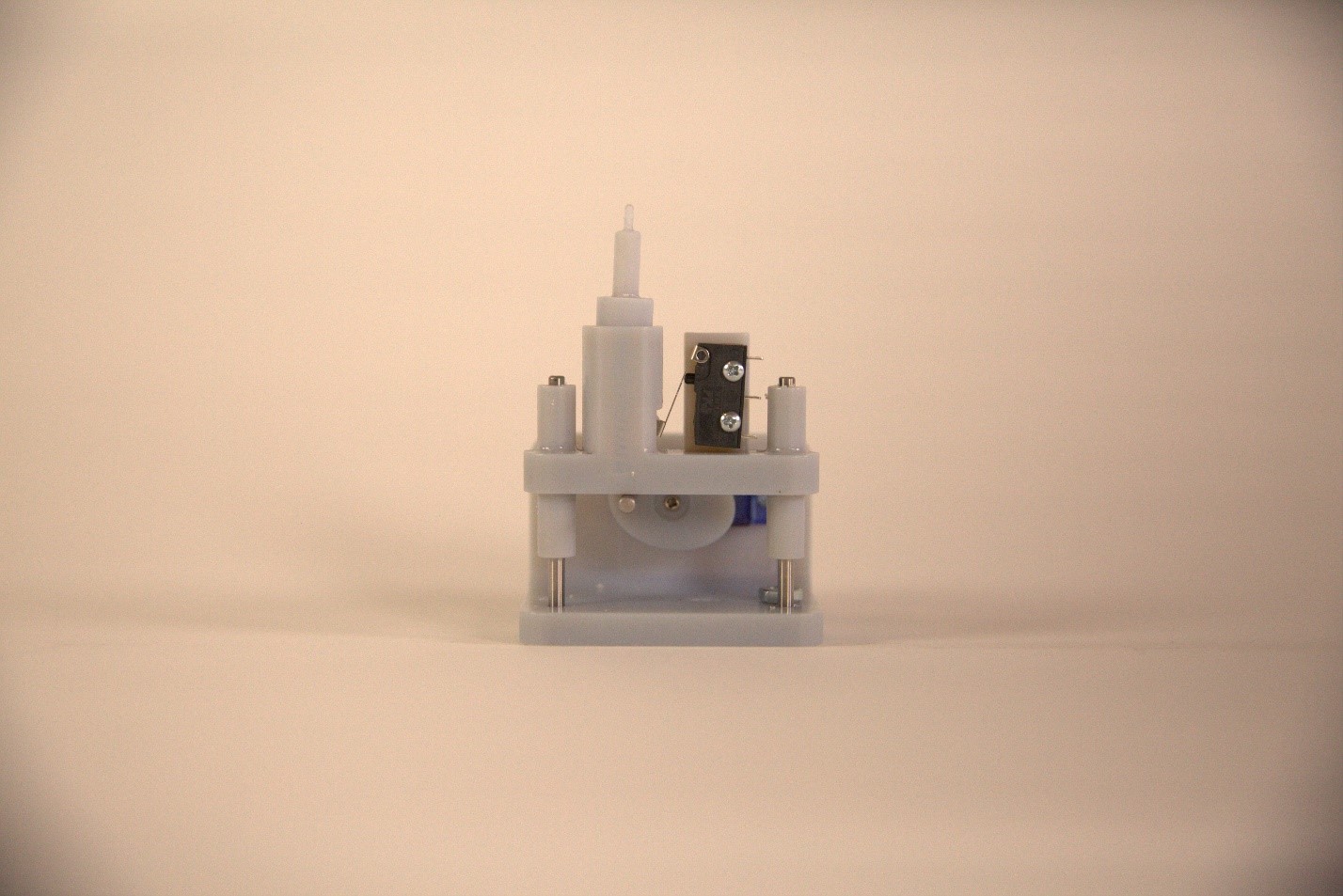
The actuator mechanism that consists of a servo which moves a platform up that contains the filament which touches the users foot. When the filament touches the foot, a spring gets compressed which activates a switch that tells the device that the filament did indeed touch the foot.
The device has four main components:
- Hardware: This is the main device which conducts the test. The hardware has 11 stepper motors for actuation, 10 limit switches for confirming that the filament contacted the foot and two capacitive touch sensors to confirm that the users’ foot is on the device
- Server: The server stores the user’s information and test data to keep track of whether the user is experiencing nerve degradation. The server is also the medium for communication between the electronics and the app.
- App: The smartphone app is the user’s main way of conducting tests. Once the user’s feet are on the device, the app allows the user to start the test and once the filament touches the users foot, the app asks them if they felt it. The app communicates with the server via get requests.
- Electronics: The brain of the hardware is an ESP32 which actuates the motors and relays sensor information to the server through get requests. (This is the section that I took ownership of)
Throughout the project, I took ownership of everything to do with electronics. This includes writing Arduino code to actuate motors, store sensor information and communicate with the server. I also did all the wiring for the electronics using a protoboard. I explored the option of fabricating a PCB but due to time constraints, this was out of scope for the class.
To simplify wiring, I made two separate protoboard modules. One that has the ESP32 microcontroller and another that distributes 5V and GND to 11 servos and 10 limit switches.
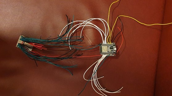
The electronics module where the board on the left is the power distribution circuit and the board on the right consists of the microcontroller
ESP32 Circuit
- White wires: The servo data cables through which a PWM signal is sent to control the servo position
- Yellow wires: Wires that connect to a metal heel liner for capacitive touch sensing
- Red and Black wires: Connects to an external power supply to supply 5V and GND to the ESP32 and sends it to the power distribution board
- Green wire: A wire that transfers the signals of the 10 limit switches to a single GPIO pin to emulate an OR gate with 10 inputs. The wire is connected to the ESP32 with an internal pull up resistor to get a digital HIGH/LOW signal input.
Power Distribution Circuit
- Red wires: Sends 5V to the power input of the servo cable
- Black wires: The GND cable for the servos and connects to one end of the limit switch
- Green wires: Connects to the other end of the limit switch which sends a 5V signal when the switch contacts are closed
The code on the ESP32 runs through a state machine which checks to see if the user’s feet are on the device and the user has told the app to start a test before actuating the motors and receiving feedback from the limit switches.

Microscope Automation and Remote Access
MIT’s Micro/Nano Engineering Laboratory runs 3 classes where student extensively use compound light microscopes to analyze experimental data. Due to restrictions caused by the COVID-19 pandemic, students were unable to have lab access and conduct these experiments.
I took on the project of finding a solution that allows remote students to have a hands-on lab experience by making the microscope controllable and viewable through the internet. I was also tasked with modifying air pressure regulators to be remote controlled so that remote students can conduct microfluidic experiments.
This project was run on a tight 1.5-month timeline and I only had access to a 3D printer and a caliper as engineering tools.
Hardware
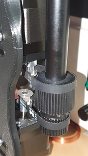
The X and Y axis was controlled with a combination of a belt drive and pulley system paired with NEMA17 stepper motors
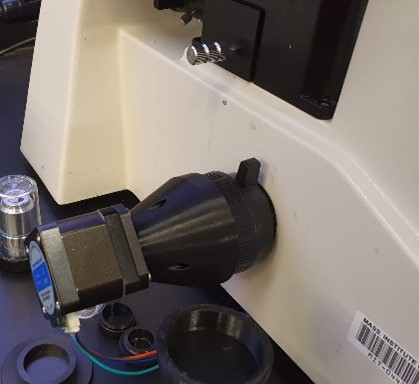
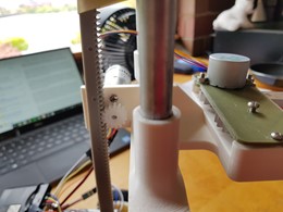
The focus stage was controlled with a minimally invasive, direct drive stepper motor meshed directly to the focus stage fine tuning shaft
Software
I wrote 3 different scripts that run in parallel on a Raspberry Pi 4 to control the microscope.
- A keyboard listener that takes the users keyboard inputs to move the microscope stage. The arrow keys move the X/Y stage, and the W/S key moves the focus stage
- A GUI which allows users to change how much the stages move and allows users to take photo/videos
- A video feed that shows the microscope image and has a display overlay that tells users their Z height and location on the slide
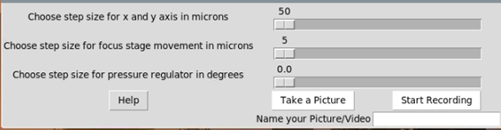
GUI with controls for controlling travel distance per click, picture/video recording and a help button which lists out all the controls and features available in the software
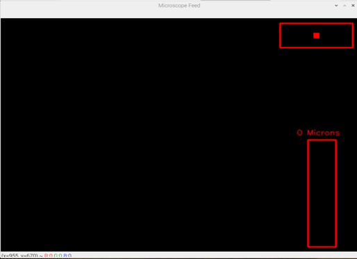
The red window on top right shows relative location on microscope slide. The bordered red square represents the whole slide and the filled square represents the section of the slide that is currently viewed. The red window on the bottom right represents how much travel is done on the Z axis. The window fills once the user starts moving up and down to give them an intuitive understanding of their relative heights and a height readout is available if they want to obtain accurate Z height measurements.
I introduced a coordinate system that allow users to control the X, Y and Z location with micrometer level precision which opens new avenues for obtaining data such as conducting Z height scans. The stages have an auto-homing feature where all three stages move to a zero position which allows users to easily change slides and have a consistent numerical height reference when taking measurements.
Interfacing Hardware and Software
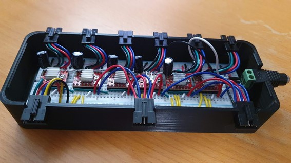
The 6 stepper motors (3 for microscope, 3 for pressure regulators) were connected to a breadboard enclosure which contained the A4988 stepper drivers. The connectors on the bottom connected 15 wires to the raspberry pi which were used to send signals to the stepper drivers. Each top connector connected to individual stepper motors to power them.
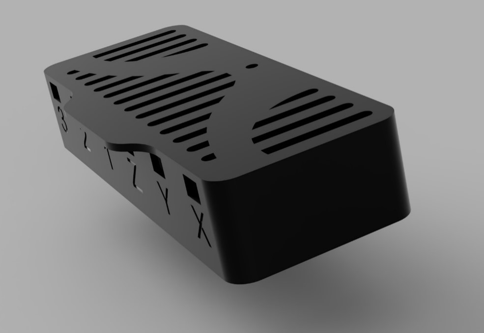
I also designed a custom enclosure which securely held the breadboard, connectors and power jack in place. The lid has cutouts for thermal management and has features that allow it to lock onto to the enclosure with a snap fit.
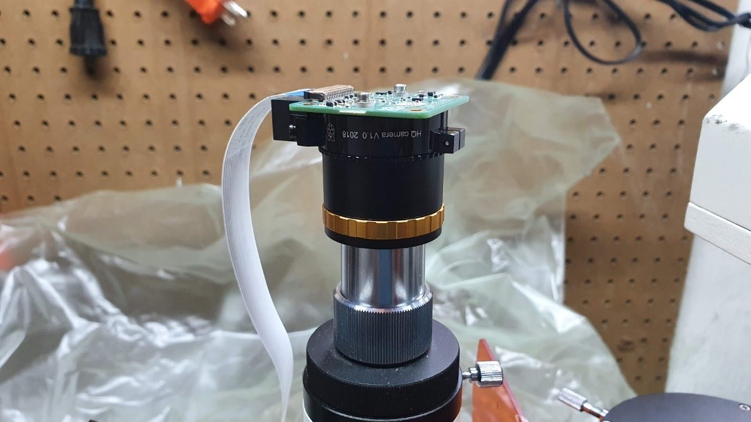
The Raspberry Pi was connected to a Sony IMX477 sensor which was connected to a microscope camera lens through a CS mount.
Below are some manuals I made on how to print, assemble and use the modified microscope.
Supernumerary Robotic Limbs
The d’Arbeloff Lab at MIT developed Supernumerary Robotic Limbs that attach to workers to improve their posture when working in environments that can lead to permanent back problems in the long run. When users want to move to a different position, they must carry or drag the limbs which weigh over 60lbs. They want to implement a walking algorithm for the robot so it can walk with the user and not be an additional weight on them.
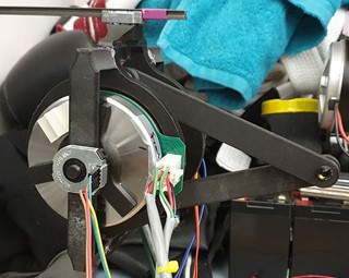
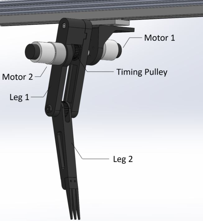
I developed small scale robotic limbs to safely test different walking algorithms since there is an inherent safety risk of testing the robot with new code with a human in the middle of it. Once the optimal algorithm has been developed, it would be scaled up to fit the full-sized robot. These tiny robotic are all 3D printable and weigh around 5lbs.
I wrote a MATLAB script that takes the leg lengths and robot mass to output the usable workspace and torque required. Using this script, I decided on a usable leg geometry for the robot.
I decided on a symmetric 5 bar linkage to drive the legs since it allows for 2DOF motion while keeping the motor mass in the body of the leg to minimize leg inertia and mimic the full-sized robot. The control loop is the main area to be tested so the difference in kinematics would not affect the tests.
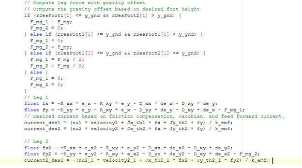
To run motion experiments, I wrote C++ code that runs on a Mbed HELIO microcontroller and transmits data in real time to MATLAB through an ethernet connection. The control algorithm I wrote was a hybrid impedance/position control feedforward algorithm that allows the robot to walk in a straight line. This is the code that researchers would modify to test their control loop.
Oil Filter Cleaning Mechanism
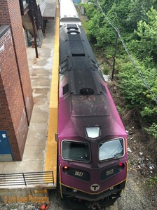
The HSP46 locomotive has an oil filter that has 60 filter candles used for filtration. These candles are replaced every three years due to gunk buildup which costs approximately $180,000 to replace them in the whole fleet. I developed and integrated a cleaning mechanism into their maintenance schedule to increase the service life of the candle.
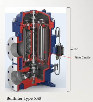
Oil filter for the locomotive engine
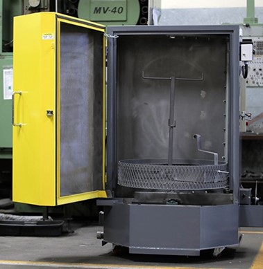
After looking at various cleaning methods, I chose a high-pressure cleaning cabinet (Ranger RD500D) used for automotive parts cleaning as the cleaning mechanism since it would be the most cost and time efficient cleaning mechanism.
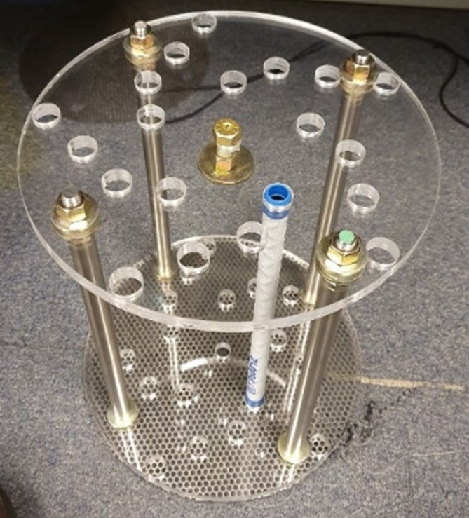
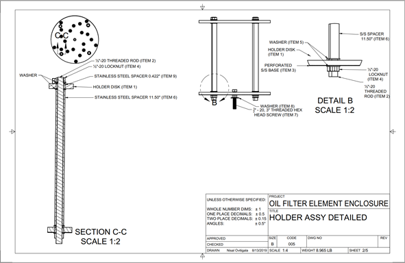
I designed and fabricated a filter candle holder to be placed inside the cabinet for cleaning. Each hole seen in the acrylic plate holds a filter candle.
I optimized the hole pattern geometry to maximize the number of filter candles that would be sprayed down. The hole pattern is based off the Fibonacci curve for optimal packing of candles.
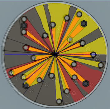
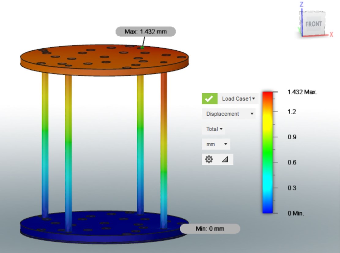
Simulation to see if all filter candles would receive water spray evenly.
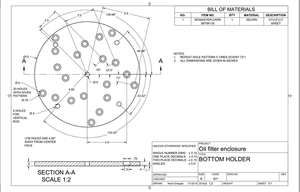
I conducted FEA simulations to see if the high-pressure water would bend the structure and cause the candles to break. The simulation assumed that the water would apply a force of 50N from a 75PSI water jet. This information was obtained from the flow rate data and has a safety factor of 3. Using the simulation results, I increased the hole size by 1.4mm to account for bending of the structure.
Headlight Redesign Project
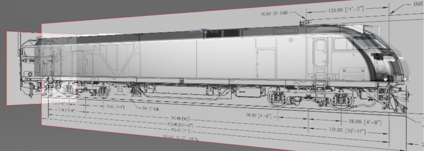
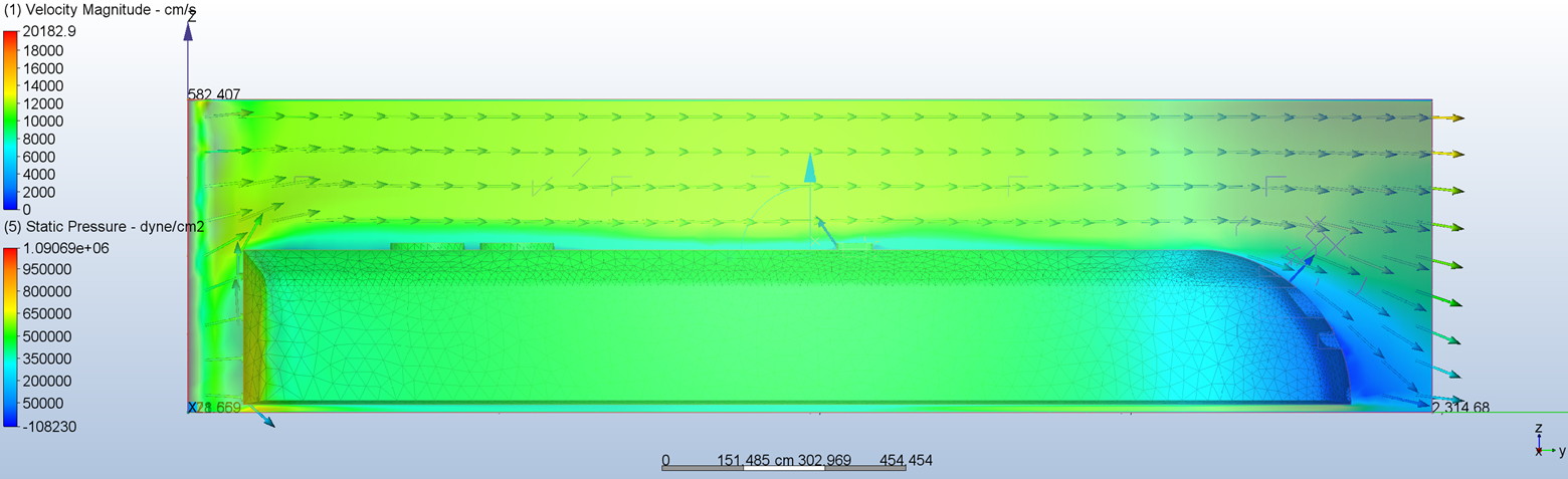
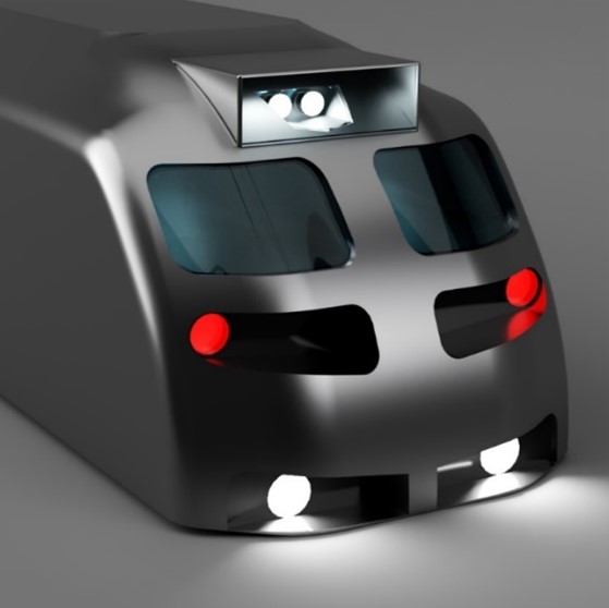
The HSP46 locomotive has an engine exhaust outlet located on top of it which causes exhaust soot to deposit on the headlight and reduce its effectiveness or sometimes block its light down to dangerous levels. I was tasked with finding a remedy to the issue.
To start off, I designed an accurate CAD model that is to be used for CFD simulations. The locomotives do not have any preexisting models, so I modelled it out of their engineering drawings.
To verify the accuracy of the CAD, I ran a CFD simulation of the locomotive to see if I could recreate the conditions for soot deposition. The simulation shows that there is a low velocity boundary layer of air flowing over the surface of the locomotive which is where soot deposition would occur.
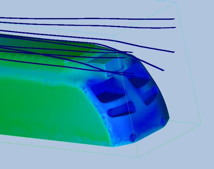
I designed a headlight cover and ran a CFD simulation to verify that the cover would get rid of soot deposition on the headlight.
Arc Reactor Yoyo and Factory Simulation
I designed a yoyo with 5 other students. Since we didn’t have lab access for the second half of the semester due to pandemic restrictions, we conducted injection molding analysis using AutoDesk MoldFlow and designed a factory to produce a million Yoyos annually using Siemens Tecnomatix.
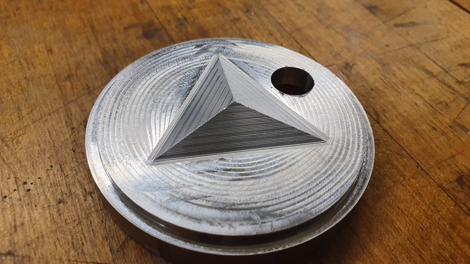
We also learned how to run and optimize CAM for machining molds for thermoforming and injection molding. Below is a thermoforming mold that I made using a CNC mill. It has a hole that was made to press fit a pin and has accurate dimensions down to 0.002” inches.
Assistive Tech. Wheelchair Attachment
Two of my classmates developed a wheelchair attachment that allow wheelchair users to traverse staircases. I joined them on further developing the product to be fully functional and scalable. The project has a provisional patent and is being funded by MIT Sandbox and the MIT PKG center with over $15,000.
Below is the first design of the wheelchair which was taken to India and user tested with over 20 wheelchair users to iterate the design
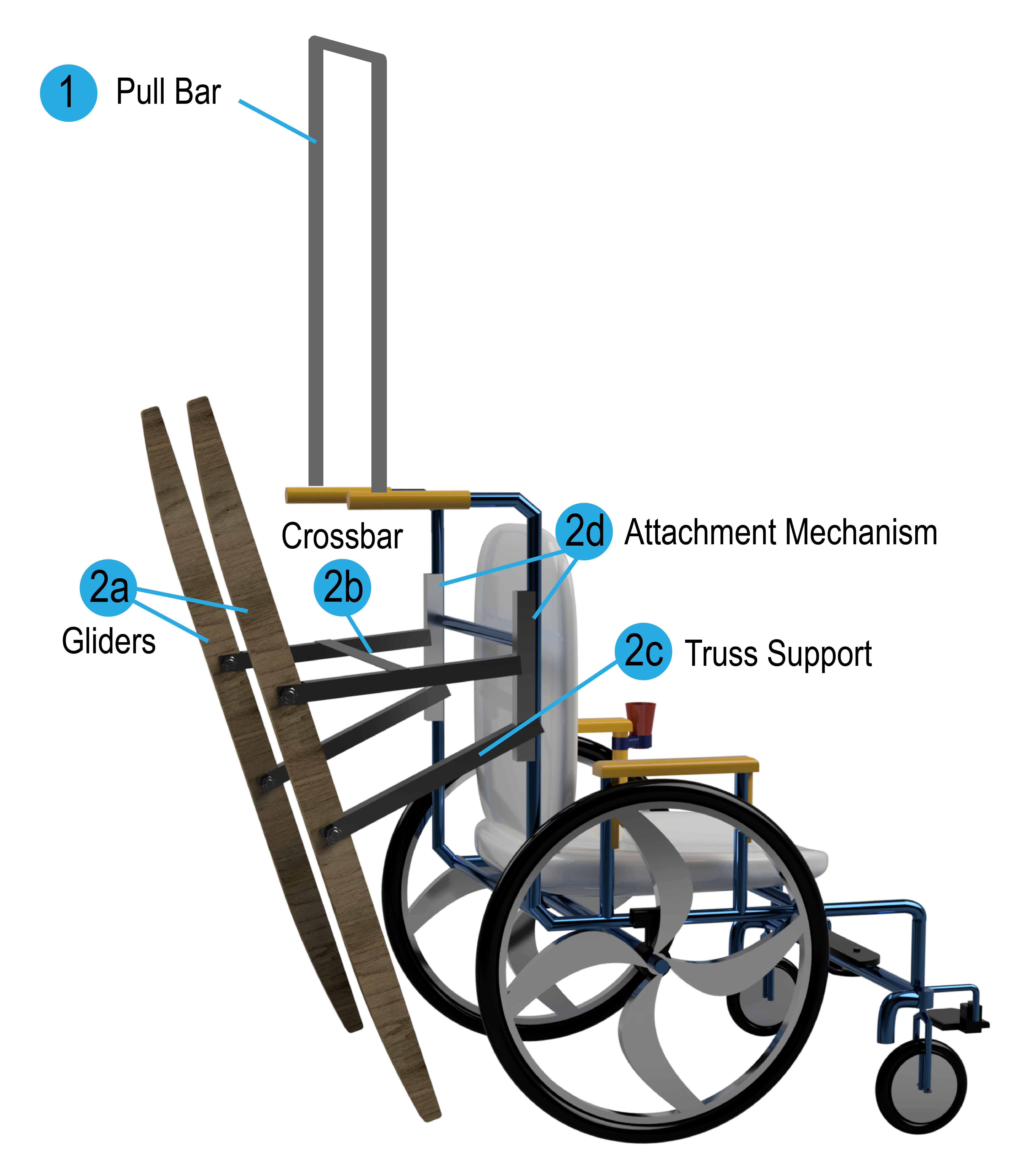
We are currently redesigning the attachment to increase its ease of manufacturability and reduce its assembly time. This design is going to be sent to the Indian Institute of Technology – Delhi to be tested with wheelchair users in the area.
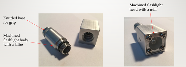
Machined Flashlight
I made a flashlight with a knurled base using a mill and lathe with square and cylindrical aluminum stock. This flashlight was made in an three day class which introduces students to machine shop tools
Remote Controlled Robot
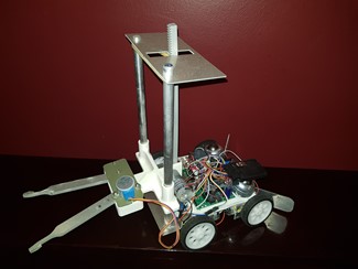
I designed, fabricated and programmed a robot to compete against other students’ robots on a game board to complete certain challenges.
The robot was programmed in Arduino and was controlled using a wireless PS2 controller. The robot also has an autonomous mode where it follows a line and pulls a handle on the game board.
The functional mechanism is a gripper that is made from water jetted aluminum. The gripper is controlled using a stepper motor and has a 3D printed housing.
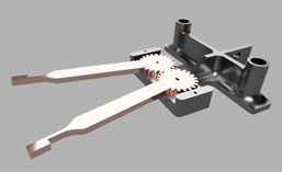
The gripper mechanism is connected to a rack and pinion system which allows it to move up and down. The rack and pinion system has two 0.5” aluminum rods for support and to reduce binding.
Lizard Inspired Robotic Leg - (2.74)
I designed and conducted tests on a robotic leg alongside three other students. We based the limb design to mimic a Shovel-Snouted Lizard which can travel a distance of over 20 times its body length in a second.
The hardware consisted of a 2 DOF robotic limb that runs on a belt drive system which is attached to a gantry that allows it to freely travel in one direction. When the limb digs into the sand, the robot is propelled forward.
I built a forward Euler simulation model in MATLAB which models the robot kinematics along with its interactions with the sand. I then ran an optimization algorithm to find the best leg angle and joint stiffness to get the highest velocity when travelling through sand. Using this information, we tested our optimal results on our hardware setup to see if it matched.
Resistive Heater Validation - Formlabs
The Fuse 1+, the newest SLS printer from Formlabs, received many upgrades which build on lessons learnt from Fuse 1. One such upgrade is an overhaul of the print chamber heating system with a more powerful resistive heating element. This new system needed thorough validation to ensure that the system is within spec, integrated with other systems, and doesn't contain any unforeseen issues
Testing efforts effort to validate this system led and conducted by me include ensuring that the system:
- Can hit temperature spec. with and without airflow
- Doesn't cause fatal damage if thermal runaway conditions arise
- Has sufficient insulation resistance to prevent electrical shorts in high humidity
- Doesn't off gas chemicals that can degrade printer optics
- Has sufficiently allocated electrical power budget without overloading 15A 120V outlets
- Has properly tuned PID parameters to maintain temperature setpoint during under/overvoltage conditions and in adverse ambient temperatures
- Doesn't degrade cosmetic powder coatings due to higher temperatures
- Can thermal cycle and properly function throughout the printers lifetime
Further efforts to understand the new heating system and integrate it with the printer include:
- Validating failure mode (element ablation) and providing data showing that power decrease/resistance increase is within acceptable limits for printer lifetime
- Providing contract manufacturers with tests and spec. ranges to accept supplier stock
- Implementing manufacturing line procedures to recover heater from failed hi-pot/shorted state
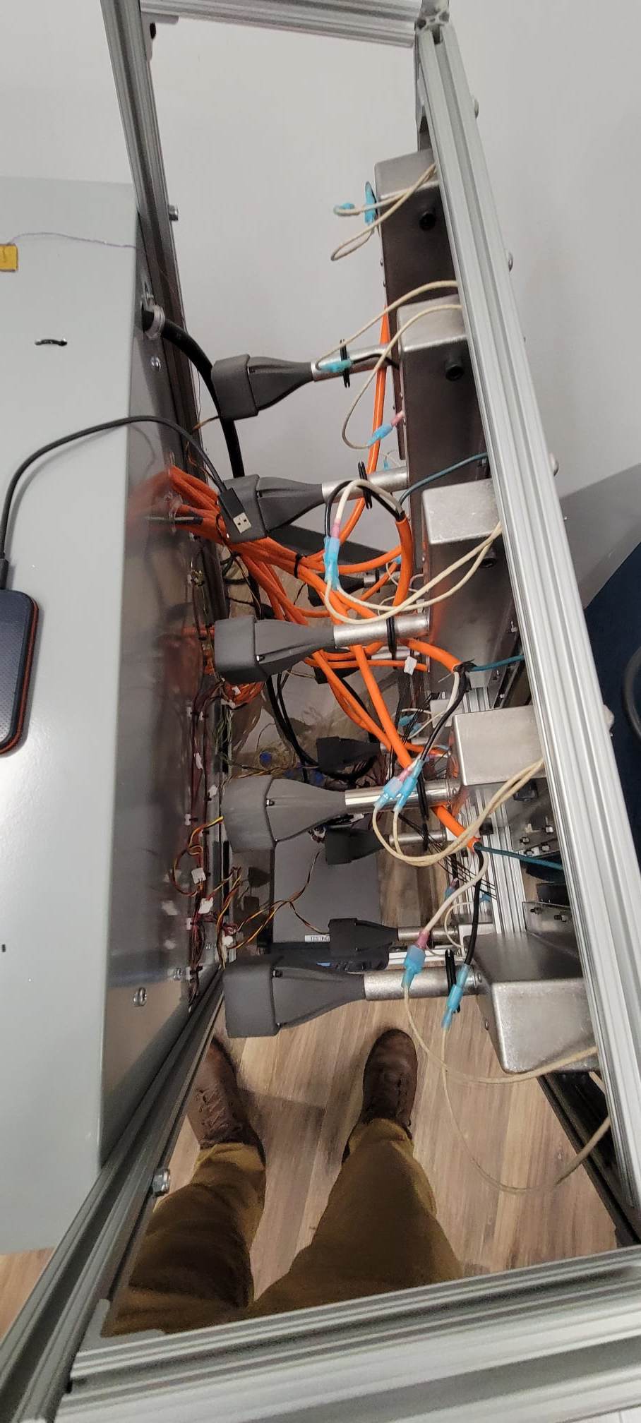
Images of test setups and data
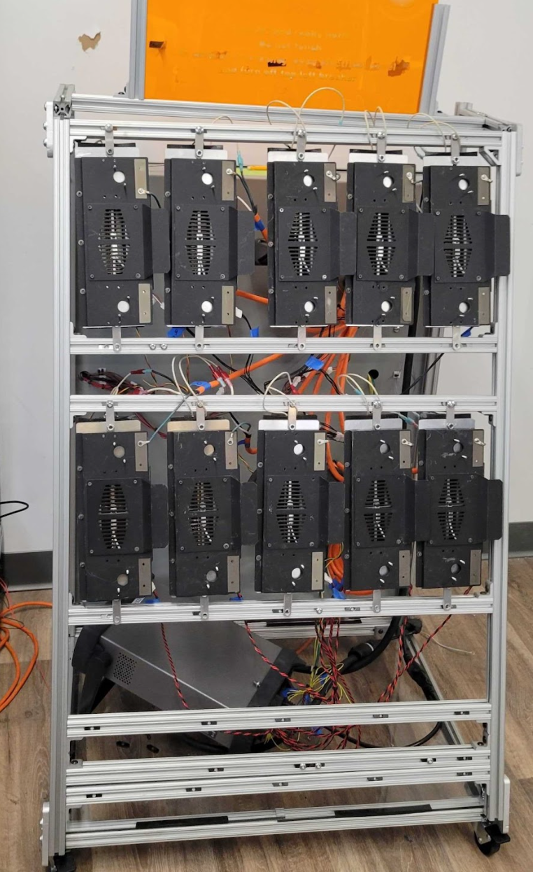
Heater thermal cycler with 10 test units. Temperature and current draw over 500 cycles collected by Keysight DAQ970
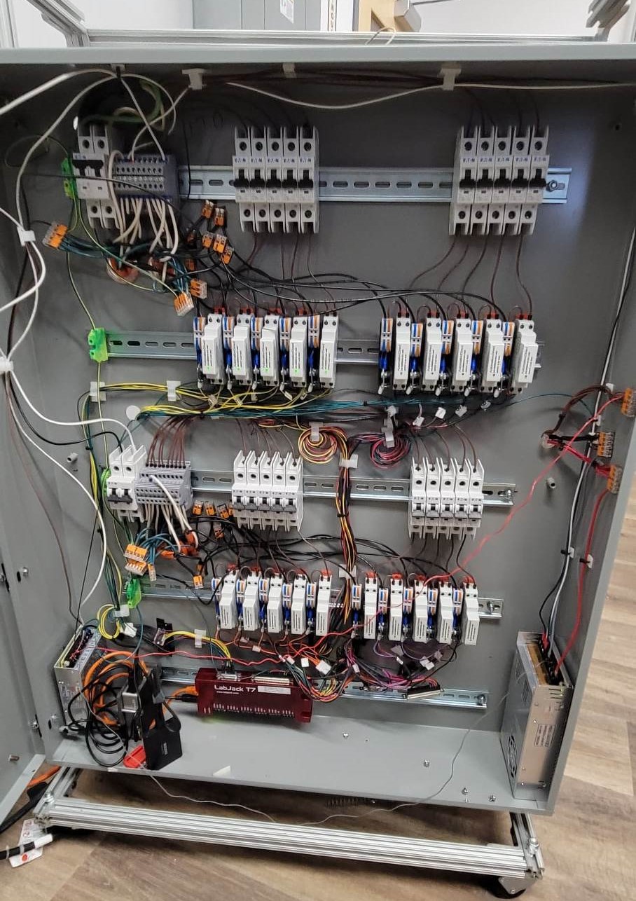
Thermal cycler project box. Features include circuit breakers and solid-state relays per heater. SSR controlled by Labjack T7 via Raspberry Pi. Separate signal PSU for minimal interference. Electrical capability to connect 20 test units for future testing
Fans in custom housing with tuned RPM to simulate in-printer flow conditions
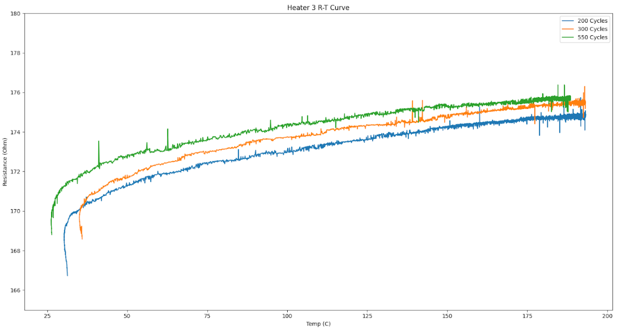
Resistance-Temperature curves showing showing clear signs of degradation over 500 thermal cycles
Print Time Reduction - Formlabs
The Fuse 1 had multiple areas for process improvements to decrease print speed. One area that had untapped time savings was through varying motor drive parameters. Motor acceleration and speed parameters were set conservatively during development, and I investigated how much we could push these motors with causing adverse side effects.
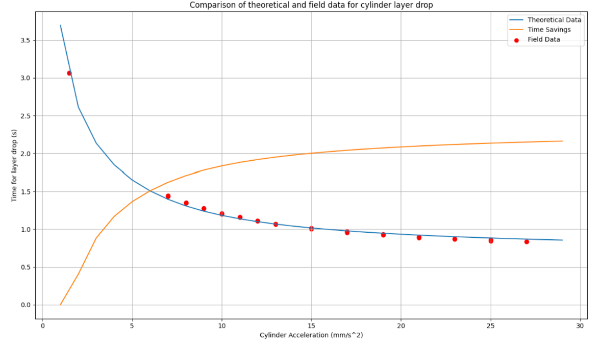
I wrote a custom script that simulates time taken for motor moves to complete. The scripts output (blue line) was verified for accuracy by comparing its results with empirical data gathered from the motors (red dot).
Z-Axis
This data gave confidence that 2 seconds can be saved through z-axis motioneverytime a new powder layer is laid over which translates to ~1.7 hours saved for a full build volume. From here, validation efforts were undertaken to ensure that higher accelerations still provided significant stall torque safety margin and primary wear component lifetime aren't affected.
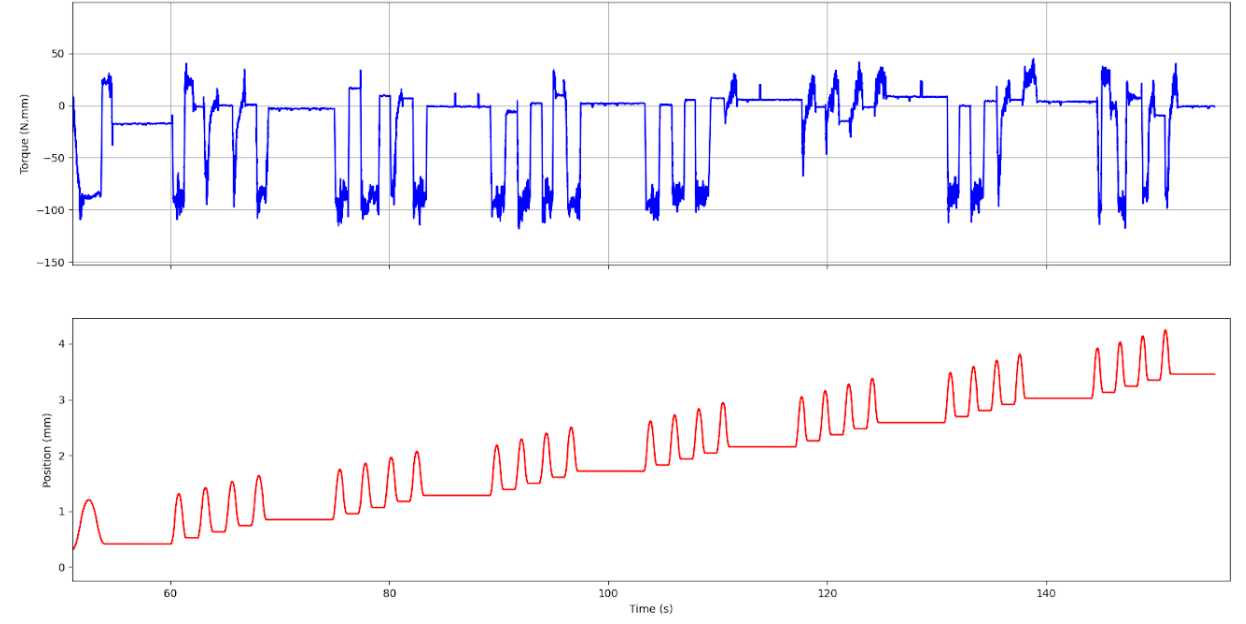
Bottom graph showing Z-axis movement via encoder with increasing acceleration. Top graph showing reaction torque of the Z-axis motor to validate that too much torque isn't used.
Lifetime tests were then conducted (N=8) with the largest acceptable mass loaded on the Z-axis. Test included regular check-in for backlash measurements to determine leadscrew nut wear.
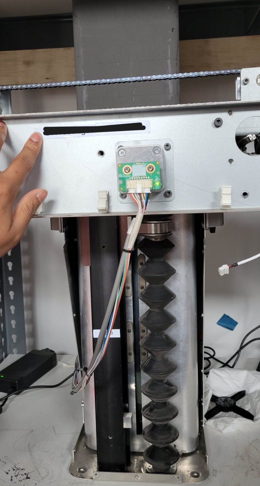
One of the lifetime rigs to drive Z-axis and capture encoder data
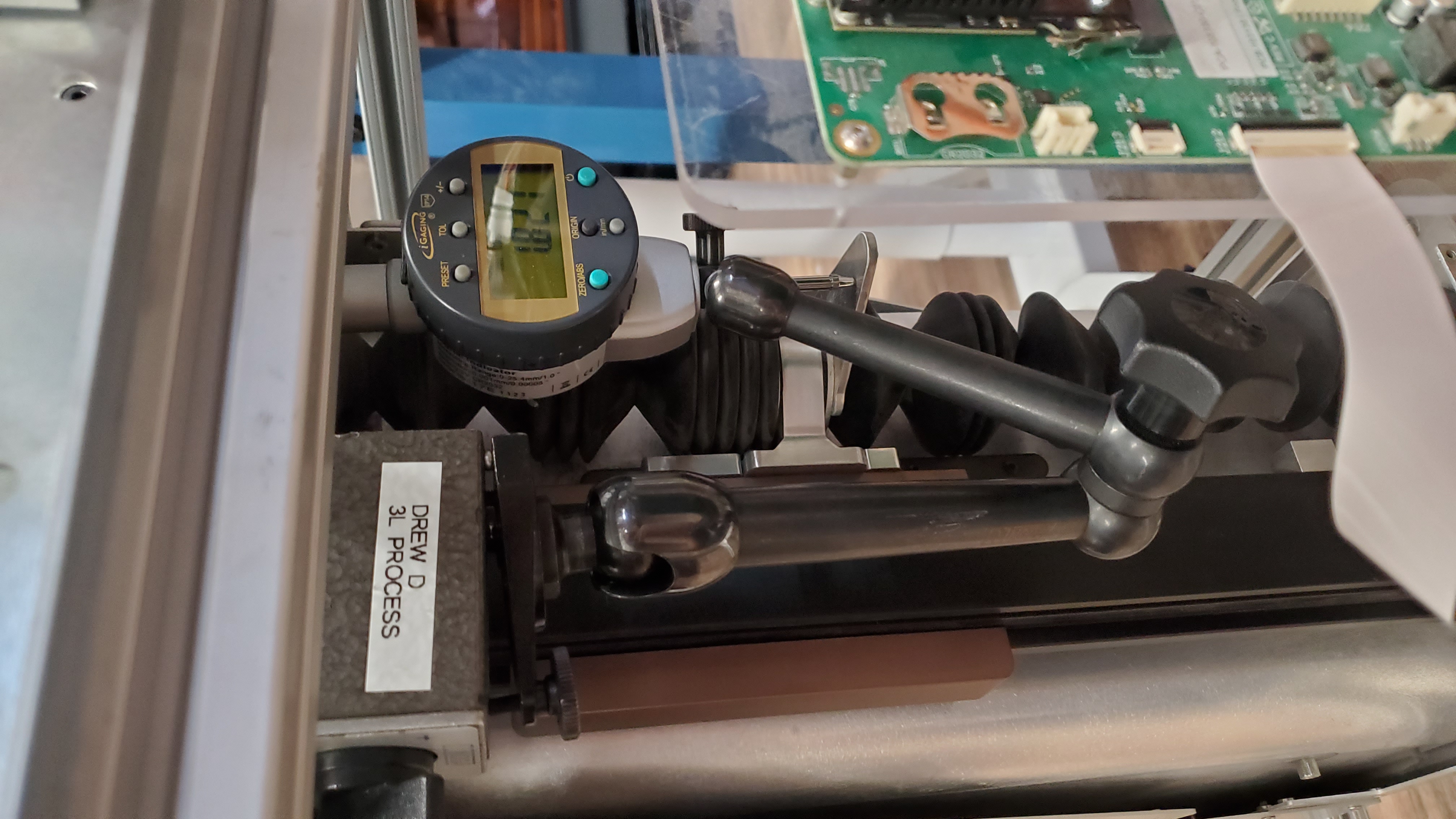
Custom dial indicator measurement setup to repeatably measure backlash
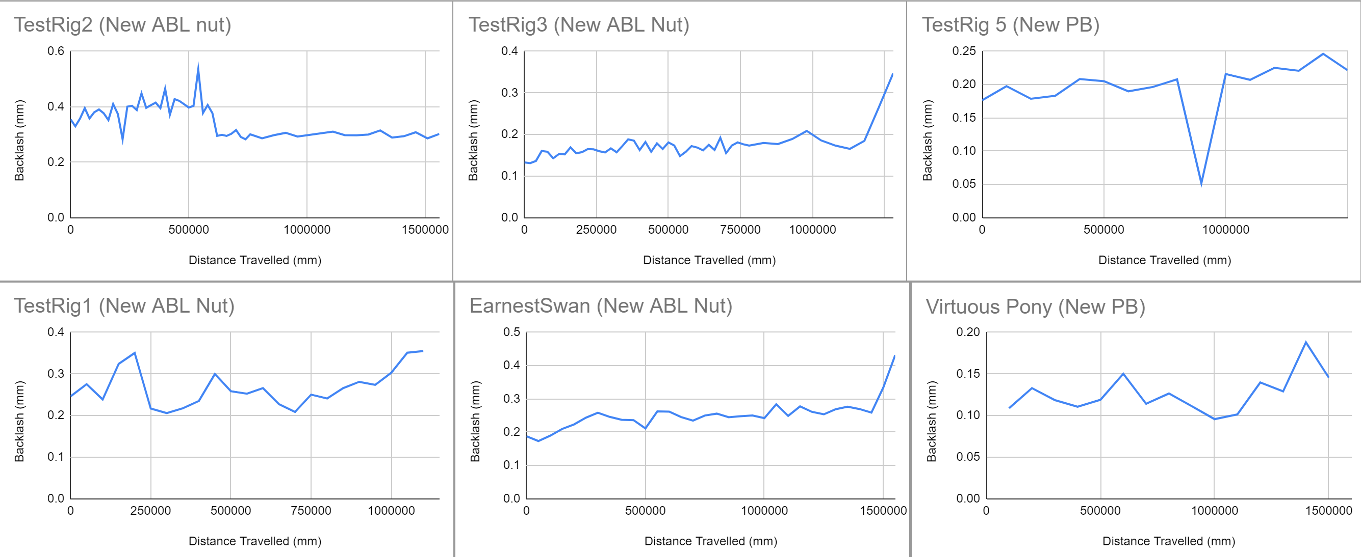
Backlash data analysis over Z-axis lifetime
Results from this test showed that wear rate and lifetime improved with higher accelerations since the leadscrew reaches a critical speed where a hydrodynamic lubricant layer reduces metal on metal contact (similar to journal bearings)
Powder Flippers
The powder flippers in the print chamber followed a similar acceleration increase with time saving analysis and torque safety margins analyzed. The limiting factor for the flippers were that they can kick up powder plumes which can degrade optical components.
To ensure powder pluming was minimized, a particulate matter sensor was purchased to quantify pluming levels. This sensor was validated by placing increasing amount of SLS powder in an enclosed chamber with a fan inducing powder pluming. The graph below shows validation data and that the sensor can be used for this purpose.
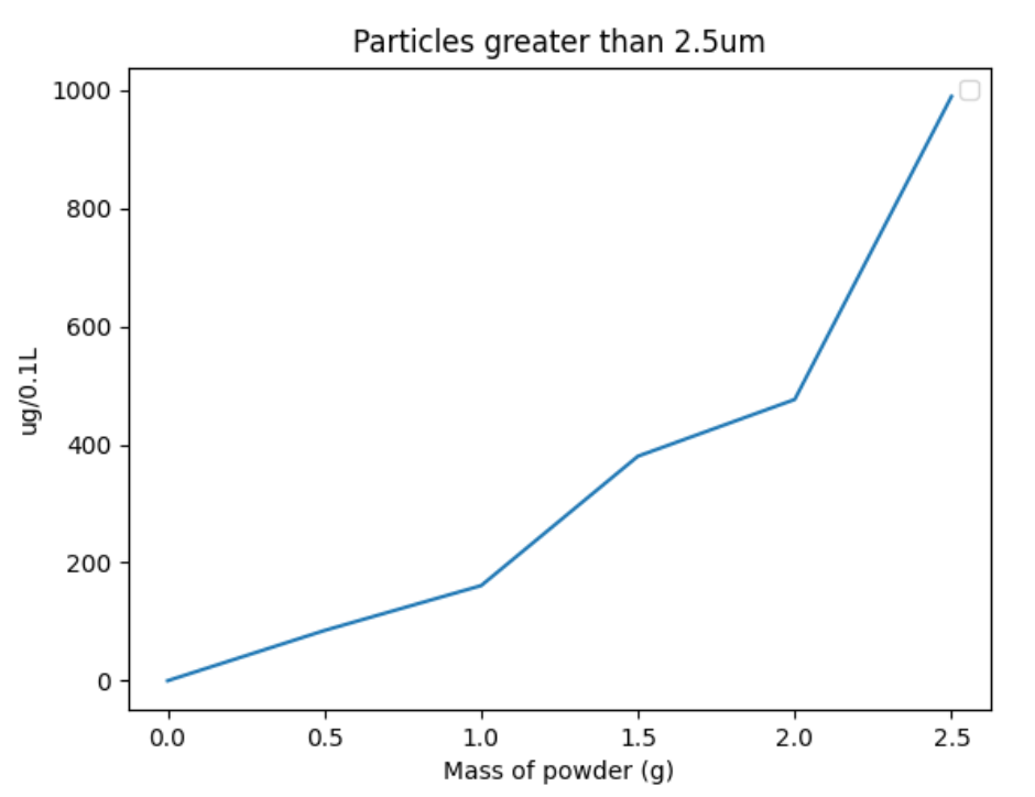
SLS Nylon 12 powder consists of particles ~100um in diameter but plumed powder consists of 1-10um particles, narrowing down the particle size region of interest. A variety of motor accelerations were tested with all SLS powders to determine optimal acceleration increase that minimizes powder pluming. ~1.5s was saved per layer with improvements. Combined with the Z-axis speedup, these changes save ~3 hours in print time (~14% faster). Further process improvements were implemented which brings the total print speed increase to 20%
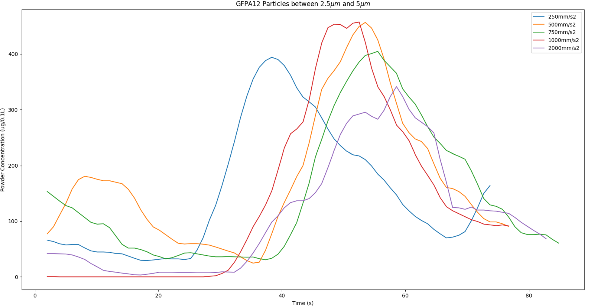
Sample raw data collected from Nylon 12 GF
Automated Laser Characterization - Formlabs
Fiber laser characterization is a manual process which requires ~6 hours of time invested per laser. This process saps engineering hours and yields low data points in the data. I developed an internal tool to automate this process and was used to characterize over 20 lasers. Characterization consists of the following:
- LIV curve generation - Understanding the relationship between output power, current draw, and voltage
- Thermal response - Magnitude and direction of output power change for a given temperature rise
- Thermal steady state - Steady state temperature when laser is at full power
- Switching response - How fast does the laser respond to on-off switching between 1Hz - 250kHz
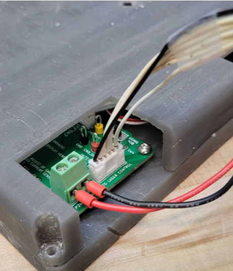
The automated tester consists of a custom PCB (developed alongside the EE team) and OTS DAQ components to control the laser driver and record feedback signals
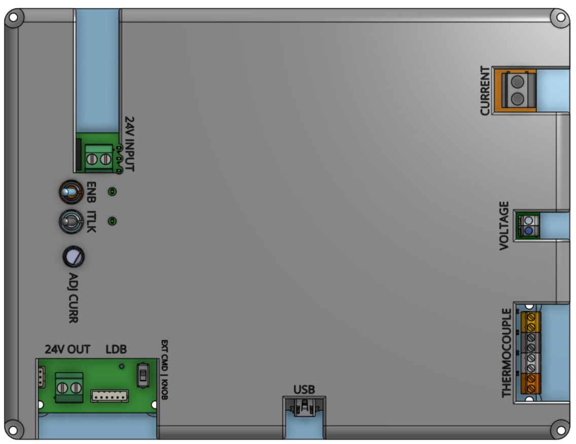
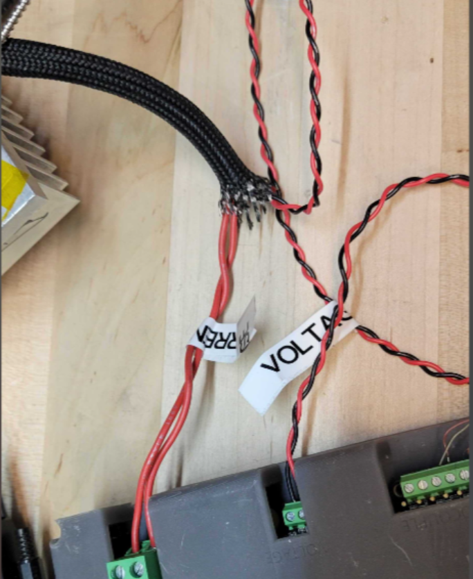
The tester can simulate interlock failures through switches and control laser power through a potentiometer or through software. A pigtail taps into the laser power wires to obtain voltage and current draw. Additional thermocouple inputs are present to monitor temperature of various parts of the laser assembly
Custom scripts I wrote allowed for additional data entries such as output power variation and time to reach thermal equilibrium. Overall, this tool (currently in active usage) has already saved over a week of engineering hours and will continue to be used for various automated test scripts that are currently in development
Extracurriculars
Activities I do outside of academic work